Tektronix Targets 3D-Image Alignment
posted:
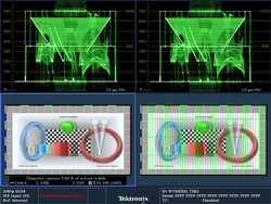
The 3D Difference Map Display can be used to effectively detect disparity between the left-eye and the right-eye images during camera alignment for 3D. The Anaglyph Display allows users to identify the parallax (3D depth) of various objects within the 3D video image. The Checkerboard Display helps the stereographer or a colorist identify any differences in brightness, focus, and various color characteristics between the left-eye and the right-eye images. For monitoring of depth of various objects within a 3D image, a Disparity Grid can be overlaid over various 3D picture displays. A Disparity Cursor is also available for precise measurement of the disparity between the left-eye/right-eye image of an object within the display.
The 3D measurements and displays are standard on the WFM8300 / WVR8300 and available as Option 3D on the WFM8200 / WVR8200. A 3D image is comprised of a Left Eye and Right Eye view feed as two separate HD-SDI signals or combined within a 3G Level B format. Within the instrument a variety of different 3D monitoring modes are available to assist the user in determining the difference between the Left Eye and Right Eye views. From this disparity difference between the two left and right images the depth of an object within the image can be determined.
advertisment
For monitoring purposes a variety of displays can be set up within the Picture mode
• Difference Map Display – A subtraction of the two luma video signals L-R or R-L to produce a grayscale difference map image to see the difference between left and right images.
• Red/Cyan Anaglyph Display – The left image is shown in red and the right image is shown in cyan, with identical left and right objects shown in monochrome. This allows the user to isolate differences between objects and gauge the depth of the object within the image.
• Green/Magenta Anaglyph Display – The left image is shown in green and the right image is shown in magenta, with identical left and right objects shown in monochrome. If an object appears in magenta and then green this indicates that the object is coming out from the screen plane. Similarly if the object appears in green and then magenta the object is behind the screen plane.
• Checkerboard Display – This picture display shows a block of the image from the left eye and then the next block shows the image from the right eye in a 16×9 checkerboard pattern. This helps the user compare the levels and color of the signal between the left and right images.
These modes help the user compare the disparity between the left and right images and can assist in interpreting the depth of the objects within the image.
For measurement of the depth of an object within the image a Disparity Grid can be overlaid over the picture with a horizontal disparity between 1 to 15% of screen width and a vertical disparity of 50%, 25%, or 10% that can be selected by the user. The horizontal and vertical position controls allow the Disparity Grid to be moved around within the picture display to gauge the depth of objects within the image.
A set of Disparity Cursors are also available for precise measurement of horizontal disparity of an object between the Left and Right Eye images. Readout is given of the pixel difference between the cursors and the percentage of disparity of an object.


